HOW THE MICROVERT REALLY WORKS
By KARL FISCHER, DJ5IL
Extremely small and highly efficient - These two properties of a fictious "super antenna" sound very attractive, not only to us radio amateurs. Unfortunately, they are physically competing since the smaller the antenna compared to the wavelength, the smaller the radiation resistance. And because in real antenna systems the losses increase with decreasing radiation resistance, efficiency drops with reduction in size.
FICTION
Jürgen Schäfer, DL7PE, claims just these two properties for his MicroVert antenna - extremely small and still highly efficient - and explains that with the practical implementation of discoveries published in 1973 by the two scientists Friedrich Landstorfer and Hans Heinrich Meinke. DL7PE wrote in his article "Progress in Design of Extremely Short Transmitting Antennas" (antenneX online magazine):
"... Its operational capability is based on theoretical principles discovered by the German scientists Prof. F. Landstorfer and Prof. H. H. Meinke [1] published as early as 1973 ... A high radiation resistance of about 30 Ohms was discovered at this time for small size monopoles being the sole secrete of its efficiency ... In spite of its very small dimensions the DL7PE-MicroVert has a high overall efficiency, which will according to my knowledge not be achieved by any other antenna of a similar small size ... According to Landsdorfer / Meinke there is an additional capacity C1 apart from the radiating capacity C2 that they called "dead-capacity". This capacity forms a closed rf-field to the near environment, similar to that of a conventional capacitor. C1 does not exist if the radiator is of 1/4 λ length, while its capacity increases steadily with the decreasing of the radiator’s physical length. Hence, the capacitance C1 becomes part of the antenna capacity and results in a new radiating resistance Rr0 of almost constant 30 Ohms regardless of the frequency used. This phenomenon actually is the key to success."
"... The dimensions of the DL7PE-MicroVert (Photo1) are extremely short in comparison to the wavelength, i.e., 0,02 λ. No special counterpoise will be required apart from the coaxial-feeder cable ... It is only the capacitor in form of an Aluminium tube that radiates in the near field, an almost pure electrical field evenly distributed along the rod ... A Monopole is always used in conjunction with a ground plane, which acts as a sort of electrical mirror. As for any other non-symmetrical antenna system, it also becomes necessary for the DL7PE-MicroVert to have a counterpoise ... It is the outer bride (shielding) of the RG 58 U, which will work for this purpose ... It seems that a part of the energy of the radiator tends to bounce back from the counterpoise. So far I could not find any clue that the counterpoise is radiating as might be expected. Only a very low electromagnetic field was found if compared with the Monopole. Thus all measurements point to the fact that radiation takes mainly place on the capacitive radiator."
DL7PE keeps "radio silence" lately. Arthur Wenzel, DL7AHW, now promotes his spraycan antenna instead which, however, in principle is nothing else but a copy of the MicroVert merely with slightly different dimensions - And, of course, also DL7AHW explains the operation with the practical implementation of the discoveries of Landstorfer / Meinke. By the way, contrary to his wild explanations the velocity factor of the coaxial cable as a transmission line has absolutely nothing to do with the positioning of the common-mode choke, because that velocity factor affects only what is going on inside of the cable, whereas the common-mode choke itself has no influence at all on the inside of the cable but only on the outer surface of the shield.
So the protagonists of these antennas argue ...
... they are extremely short monopoles because the coax-segment between the "radiator" and the common-mode choke is merely a non-radiating "cold" counterpoise and ...
... they exhibit an exceptionally high efficiency because the discoveries of Landstorfer / Meinke were applied, according to which the radiation resistance of extremely short monopoles is about 30 Ohm.
Is that true ?
SCIENTIFIC BACKGROUND
Whoever attentatively reads the article by Landstorfer / Meinke will discover that their core statements were misunderstood and unduly reduced by DL7PE. So well-founded scientific discoveries are brought into discredit and misused as an explanation for the supposed exceptionally high efficiency of the MicroVert. On order to counteract and to make that article also accessible for non-German-speaking interested parties, I translated it into English.
German original:
"Ein neues Ersatzbild für die Impedanz kurzer Strahler" (PDF, 1071 KB)
English translation:
"A New Equivalent Circuit for the Impedance of Short Radiators" (PDF, 322 KB)
In fact Landstorfer / Meinke discovered an original radiation resistance Rso of about 30 Ohm for monopoles which interestingly is almost independent of frequency and rod diameter and which describes space as an absorber for the radiated energy. Unfortunately that original radiation resistance is not directly accessible, which indeed would allow for smallest and highly efficient antennas, but is transformed into the actually usable radiation resistance Rs by a capacitance C2 in series with Rso and a capacitance C1 in parallel with that series combination, which yields just that new equivalent circuit for the impedance of short radiators (the transforming action of C1 and C2 can be visualized nicely in the Smith-chart). The division of the total antenna capacitance into these two capacities is described very clearly both in quality and in quantity on the basis of the time-dependent course of wave detachment in the near field of antennas - a subject which has been intensively addressed by Prof. Dr. Landstorfer with many interesting publications.
Now it appears that any monopole has a characteristic limiting point. Electric field lines emanating from the radiator above that point tear up, travel out into space and thus contribute to the radiation of energy, which is why the antenna capacitance above that point is called SPACE CAPACITANCE (in the equivalent circuit C2 in series with Rso). However, electric field lines emanating from the radiator below that point do not tear up but migrate back to the generator. Consequently they merely represent reactive power and do not contribute to the radiation of energy, which is why the antenna capacitance below that point is called DEAD CAPACITANCE (in the equivalent circuit C1 in parallel with the series combination of Rso and C2).
The height of that charactersistic limiting point is almost independent of the rod diameter and moves on a monopole of constant length from the tip of the radiator at the frequency zero with increasing frequency downwards to the feedpoint at the λ/4 resonance frequency. According to Fig. 7 of the article, at the frequency zero the whole rod represents dead capacitance and no wave detachment takes place. The limiting point of a 0.1 λ long rod, for example, lies at about 2/3 of the height, so only the upper third of the radiator represents space capacitance but the lower two thirds dead capacitance. And finally the limiting point of an electrically 0.25 λ long rod lies right down at the feedpoint, the whole rod represents space capacitance and hence contributes to radiation. So for constant rod diameter and frequency with the shortening of the radiator the space capacitance C2 increases and the capacitive reactance of the antenna impedance increases, but at the same time the dead capacitance C1 increases and thus Rso = 30 Ohm is transformed into an ever smaller usable radiation resistance Rs.
So Landstorfer / Meinke explain why and how the radiation resistance and as a result also the efficiency are decreasing with the shortening of the radiator and why for a rod of uniform diameter that diameter has no influence on the radiation resistance Rs. And they show that constructive measures increasing only the dead capacitance won't do any good, but on the contrary will decrease the usable radiation resistance Rs, whereas by decreasing the dead capacitance and increasing the space capacitance the transformation of Rso is getting more favourable and the usable radiation resistance Rs is increasing. In principle that's nothing new and we know that e.g. a capacity hat increases the radiation resistance. However, the article explains that behaviour in quality as well as in quantity and derives it from field examinations.
NEC-SIMULATION
The DL7PE-MicroVert is constructed as follows: The feeding coaxial cable is wound as a common-mode choke on a ferrite core slightly less than λ/4 from its end, this end section of the coaxial cable will be called coax-segment consequently. At the end of the cable its shield is left open and its inner conductor is connected via a loading-coil to a thick and short tube, which will be called tube-segment consequently. DL7AHW utilizes spray- or beer-cans and the like as extremely thick and short tubes in his spraycan antenna.
The coax-segment can be replaced electromagnetically equivalent by a simple conductor with the same diameter and length and the antenna then can be fed in the classic way between that conductor and the loading-coil with coaxial cable via a current-balancing device (e.g. common-mode choke = 1:1 Guanella) - This equivalent configuration reveals the true nature of the MicroVert and at the same time enables easy antenna simulation. Following are the results of my simulation with EZNEC+ v. 4.0.
A typical MicroVert for the 40m amateur-radio band could be made of, for example, a coax-segment 7.8 m in length and 5 mm in diameter (RG-58), a tube-segment 0.8 m in length and 22 mm in diameter, and a loading-coil of L = 47 uH und Q = 100. DL7PE wrote in his article:
"... high demands on the Q of the coil will not be required. This leads us to a rather slim coil design with a diameter of around one inch and small wire diameters, e.g., #18 for 150 watts pep."
It will turn out that this assessment is wrong. Apart from that, the assumed quality factor of Q = 100 is very optimistic for a 47 uH air-coil made of AWG #18 (approx. 1 mm) wire, therefore the efficiencies will in practice more likely fall short off the simulated values.
The NEC-Modell of this antenna structure consists of two wires:
1) The coax-segment is simulated by a wire 7.8 m in length and 5 mm in diameter with 60 segments.
2) The tube-segment with loading-coil is simulated by a wire 0.8 m in length and 22 mm in diameter with 6 segments plus a load of 47 uH and 21 Ohm in series (corresponding to Q = 100 @ 7.05 MHz) on segment #1.
Note: EZNEC ahows the "Average Gain" after "FF Plot" in 3D-mode in the lower part of the main window. This value is the ratio of the radiated power averaged during the 3D-plot across the whole sphere (free space) or hemisphere (above ground) to the power supplied by the generator and consequently nothing else than the efficiency η in dB of the antenna system.
At first, these two wires are simulated one at a time as a monopole over perfect ground. The source is placed on the segment connected to ground, the wire loss is zero and the frequency is 7.05 MHz. The following values result for Impedance (Z) and "Average Gain" (Gavg):
coax-segment: Z = 16.6 - j 176 Ohm, Gavg = 0.0 dB
tube-segment: Z = 21.2 + j 178 Ohm, Gavg = -21.0 dBThe coax-segment ist capacitive (resonant frequency = 9.3 MHz), exhibits a radiation resistance of Rs = 16.6 Ohm and the "Average Gain" is 0.0 dB corresponding to an efficiency of η = 100 %.
The tube-segment is inductive (resonant frequency = 6.75 MHz), exhibits an extremely small radiation resistance of 21.2 Ohm - 21.0 Ohm (loss-resistance of the coil) = 0.2 Ohm and the "Average Gain" is -21.0 dB corresponding to an efficiency of η = 0.8 %.
The simulated radiation resistance of the tube-segment af about 0.2 Ohm is confirmed by the known equation for the radiation resistance of a short monopole according to which Rs = 40 π² (h / λ)² = 395 (0.8m / 42.6m)² = 0.14 Ohm. The antenna efficiency η can also be calculated directly from the radiation resistance Rs and loss resistance Rv with η [%] = 100 * Rs / (Rs + Rv). For the tube-segment operated as a monopole against a non-radiating counterpoise Rs = 0.2 Ohm and Rv = 21 Ohm so η = 100 * 0.2 Ohm / (0.2 + 21) Ohm = 0.9 % which yields a gain of 10 * log (0.009) = -20.5 dB. This value is in good agreement with -21 dB calculated by EZNEC.
Now the long wire is aligned horizontally and at one end connected to the lower end of the short vertical wire. The source is placed on the end segment of the horizontal wire which is connected to the vertical wire. This structure now represents the complete MicroVert with horizontally polarized coax-segment and vertically polarized tube-segment. In free space the following values result for Impedance (Z) and "Average Gain" (Gavg):
Z = 39.7 + j 2.5 Ohm, Gavg = -7.8 dB
The antenna is almost resonant on 7.05 MHz (SWR = 1.27 @ 50 Ohm) and its impedance Z in the feedpoint, as expected, almost exactly equals the series combination and hence the sum of the monopole-impedances 16.6 - j 176 + 21.2 + j 178 Ohm = 37.8 + j 2 Ohm. The "Average Gain" is -7.8 dB corresponding to an efficiency of η = 17 %, so 83 % of the power delivered by the generator are converted to heat in the loss-resistance of the coil. The radiation patterns in the plane perpendicular to to the short wire (azimuth pattern @ 0° elevation) as well as in the plane perpendicular to the long wire show the maximum of the vertically polarized field component about 18 dB below the maximum of the horizontally polarized field component. So the short vertical tube-segment of the MicroVert radiates only about 1.6 % of the power that is radiated by the long horizontal coax-segment ! This value, as expected, almost exactly corresponds to the theoretical ratio of the radiated power of both segments, which on the assumption of equal currents results from the ratio of their radiation resistances as 10 * log (0.2 Ohm / 17 Ohm) = -19.3 dB.
High above perfect ground, impedance and "Average Gain" correspond to their free-space values. However, the more the antenna structure is lowered towards ground, the smaller gets the real part of the impedance and the larger gets the negative "Average Gain" and hence the loss. The simulation yields the following values for various heights (h) of the long wire (coax-segment) above perfect ground:
h = 10.00 m --> Z = 40.3 + j 5.8 Ohm, Gavg = -7.5 dB
h = 05.00 m --> Z = 35.3 + j 5.9 Ohm, Gavg = -11.2 dB
h = 01.00 m --> Z = 32.6 + j 24.7 Ohm, Gavg = -20.6 dBThe same effect with only slightly differing values appears when the perfect ground is replaced by a large conductve structure simulated by a 20 m x 20 m wire-grid with 1 m grid-width. The simulation yields the following values for various heights (h) of the long wire (coax-segment) above the wire-grid in free space:
h = 10.00 m --> Z = 39.7 + j 6.6 Ohm, Gavg = -7.8 dB
h = 05.00 m --> Z = 35.0 + j 6.4 Ohm, Gavg = -11.6 dB
h = 01.00 m --> Z = 32.8 + j 20.9 Ohm, Gavg = -18.8 dBWith decreasing height of the coax-segment its coupling to the perfect ground or the large conductive structure increases and simultaneously its radiation resistance decreases, therefore impedance and "Average Gain" approach the values of the tube-segment operated as a monopole. With real ground this effect is less pronounced, but the ground losses are increasing and the efficiency decreasing as well. The larger the conductive structure and the more perfect its geometrical symmetry with reference to the location of the tube-segment, the more perfect is the cancellation of the far-fields associated with the currents flowing in that structure, the less it radiates and the smaller its radiation resistance and also the radiation resistance of the tightly coupled coax-segment - Finally only the short and inefficient tube-segment remains as a vertical monopole on a non-radiating reflective plane as the counterpoise, which could be replaced by a point-symmetric and hence non-radiating set of radials. The "Average Gain" of a MicroVert then typically is about -21 dB corresponding to an efficiency of merely η = 0.8 % ! That is the case if, for example, the coax-segment is lying on a tin roof or on well conducting ground.
It must be emphasized that this dramatic loss increase coming along with approaching a large conductive structure is not caused by losses within that structure, but solely by the fact that the coax-segment contributes less and less radiation resistance. And of course folding or coiling up of the coax-segment has in principle the same effect.
Prior to the analysis of the near-field a short digression ...
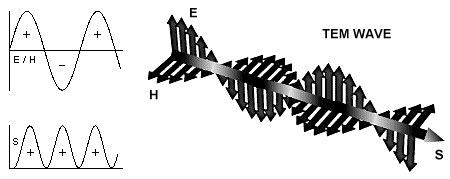
The POYNTING VECTOR (named after the physicist John Henry Poynting) is the cross-product of the electric E-field and magnetic H-field vectors S = E x H and describes the energy flow in an electromagnetic wave field. It points in the direction of energy flow and its magnitude is the energy flux density, the energy per time unit through an area unit perpendicular to the direction of flow. The physical terms energy flow and power are equivalent and consequently also the terms energy flux density and power density:
energy / (area * time) = power / area = J / (m² s) = W / m² = N / (m s)
By the way: "power flow" is a screwy term which, unfortunately, it is very often incorrectly used even by experts. POWER DOES NOT FLOW, IT IS THE RATE AT WHICH ENERGY FLOWS (power = energy / time = J / s = W) !
In periodic wave fields E-field and H-field vectors are perpendicular to each other and both oscillate transversely, i.e. perpendicular to the direction of propagation of the electromagnetic wave (hence the term Transversal ElectroMagnetic or short TEM wave), while the Poynting vector oscillates perpendicular to both the E-field and H-field vector and thus longitudinal, i.e. in the direction of propagation, at twice the frequency of the electromagnetic fields.
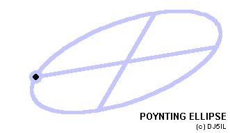
If real and reactive power are present and if their direction differs, the tip of the Poynting vector describes an ellipse during each half cycle. Because its origin also lies on the ellipse, the energy flux density passes through the maximum and through zero twice per cycle. The vector from its origin to the center of the ellipse is the time-averaged Poynting vector, it points in the direction of the real power and its magnitude is the effective real power density, irradiance or intensity. Doubling the time-averaged Poynting vector yields the maximum real power vector, its tip lies on the ellipse again and hence it constitutes one ellipse diameter. So the real power pulsates twice per cycle between zero and maximum density without changing direction and orientation. The true enegry flow is the superposition of that real power with an oscillation caused by the reactive power, energy that merely sloshes back and forth with a net flux of zero. Therefore the reactive power passes through its maximum density at two points on the ellipse but with opposite sign. These are the tips of the two maximum reactive power vectors, shifted to the tip of the real power vector and hence to the center of the ellipse. So these two maximum reactive power vectors and the maximum real power vector constitute two conjugated ellipse diameters which are identical with the two main axes of the ellipse only if the directions of both power components are orthogonal. If only real or reactive power are present or if both are present and their directions correspond, the ellipse degrades into a straight line.
An electromagnetic wave transports energy and since energy has mass (E = m c²) it also transports mass and momentum and exerts pressure. This radiation pressure in Pascal (N/m²) results from the division of the irradiance by the speed of light for an absorbing surface, for a reflective surface the radiation pressure is twice as high.
The phase-delay between real and reactive power is always 1/4 cycle or 90° of their own frequency which is twice the E-field and H-field frequency. When the tip of the Poynting vector passes through its origin, the real power vector and the reactive power vector are zero at the same time. After 1/4 cycle the real power passes through its average value and the reactive power through its first maximum, after 1/2 cycle the real power passes through its maximum and the reactive power through zero again, after 3/4 cycle the real power passes through its average value again and the reactive power through its second opposing maximum and finally after one cycle the ellipse is completed and the Poynting vector is zero again. So the reactive power vector like the real power vector does not change direction, but in contrast to that it changes sign and consequently orientation. The addition of both vectors yields the Poynting vector with its tip describing an ellipse.
Applied to antenna fields, real power is energy flow out into space or radiated power, whereas reactive power is quasi-stationary energy which is merely pumped back and forth between E-field and H-field. In the FAR-FIELD of an antenna the radiated power predominates and with increasing distance the share of reactive power becomes insignificant. Then E-field and H-field are in phase, that is they reach their maximum and minimum at the same time, which is why the Poynting ellipse degrades into a straight line. And they have a constant ratio of E / H = Zo = 377 Ohm, the characteristic impedance of free space. And where is the energy when both fields go through zero ? It has moved on ! Fieldstrength and radiated power only go through zero if one observes a fixed point in space. With their maximum, however, one would move along with the energy in space exactly like a surfer on the crest of a wave. Approaching the antenna, the phase-delay between E-field and H-field increases and with it the share of reactive power, which represents energy that is stored alternately in both fields and exchanged between them. Thus the straight line, which the tip of the Poynting vector describes, develops into a very slim ellipse which gets thicker, becomes a circle and finally gets thinner and thinner in the other direction. Then we are in the REACTIVE NEAR-FIELD where the reactive power predominates.
Since the E-field inside a perfect conductor is zero, the Poynting vector is also zero - which means that the energy flow does not take place inside of the conductor by electric current but in the surrounding space by the electromagnetic wave. And since the E-field vector always stands perpendicular right on the surface of a perfect conductor, the Poynting vector is always tangential right at the surface - which means that a perfect conductor is not able to emit or absorb but only to reflect energy and to act as sort of a waveguide. It follows that antennas do not radiate originally but merely reflect or scatter electromagnetic energy that flows from the generator through the space surrounding the conductors of the feedline to the feedpoint, where it is spewed out in all directions to move partly on curved paths through space to the conductors of the antenna structure. From that point of view, the current in the antenna conductor is not the cause for radiation but merely a response to the electromagnetic wave surrounding it, like the rustling of pebbles on a riverbank as the bow wave of a boat passes by. There remains the question: where is the energy originally emitted ?
It must be noted that the interpretation of the Poynting vector as the local energy flow is sometimes criticized as being suspect or even inadmissible. As a response to that criticism I would like to quote Richard Feynman, the ultimate physicist and greatest science lecturer of all time, from "The Feynman Lectures on Physics: Mainly Electromagnetism and Matter", 1964:
"Before we take up some applications of the Poynting formulas [Eqs. (27.14) and (27.15)], we would like to say that we have not really "proved" them. All we did was to find a possible "u" and a possible "S". How do we know that by juggling the terms around some more we couldn't find another formula for "u" and another formula for "S" ? The new S and the new u would be different, but they would still satisfy Eq. (27.6). It's possible. It can be done, but the forms that have been found always involve various derivatives of the field ...
There are, in fact, an infinite number of different possibilities for u and S, and so far no one has thought of an experimental way to tell which one is right ! People have guessed that the simplest one is probably the correct one, but we must say that we do not know for certain what is the actual location in space of the electromagnetic field energy. So we too will take the easy way out and say that the field energy is given by Eq. ( 27.14). Then the flow vector S must be given by Eq. (27.15) ...
Anyway, everyone always accepts the simple expressions we have found for the location of electromagnetic energy and its flow. And although sometimes the results obtained from using them seem strange, nobody has ever found anything wrong with them - that is, no disagreement with experiment. So we will follow the rest of the world - besides, we believe that it is probably perfectly right ...
Finally, in order to really convince you that this theory is obviously nuts, we will take one more example - an example in which an electric charge and a magnet are in rest near each other - both sitting quite still. Suppose we take the example of a point charge sitting near the center of a bar magnet ... Everything is at rest, so the energy is not changing with time. Also, E and B are quite static. But the Poynting vector says that there is a flow of energy, because there is an E x B that is not zero. If you look at the energy flow, you find that it just circulates around and around. There isn't any change in the energy anywhere - everything which flows into one volume flows out again. It is like incompressible water flowing around. So there is a circulation of energy in this so-called static condition. How absurd it gets ! Perhaps it isn't so terribly puzzling, though, when you remember that what we called a "static" magnet is really a circulating permanent current. In a permanent magnet the electrons are spinning permanently inside. So maybe a circulation of the energy outside isn't so queer after all. You no doubt begin to get the impression that the Poynting theory at least partially violates your intuition as to where energy is located in an electromagnetic field ... The circulation of energy around a magnet and a charge seems, in most circumstances, to be quite unimportant. It is not a vital detail, but it is clear that our ordinary intuitions are quite wrong."
After that brief explanation of the Poynting vector now we finally get to the near-field analysis of the MicroVert. For this purpose, also the long wire (coax-segment) is aligned vertically and and is now lined up with the short wire (tube-segment) on the z-axis of the EZNEC coordinate system, so that the free end of of the short wire is located at (x / y / z) 0 / 0 / 0.8 m and the free end of the long wire at 0 / 0 / -7.8 m. In free space the following values result for a generator power of 100 W:
1) At a distance of 0.1 m from the center of the tube-segment (0 / 0.1 / 0.4 m) EZNEC yields the following E-field and H-field values:
Ex Mag = 1.296E-11 Veff/m
Ex Pha = 2.38°
Ey Mag = 7833.67 Veff/m
Ey Pha = -90.13°
Ez Mag = 263.95 Veff/m
Ez Pha = 89.96°
E tot = 7838.12 Veff/m
Hx Mag = 1.404 Aeff/m
Hx Pha = 179.86°
Hy Mag = 1.785E-10 Aeff/m
Hy Pha = 1.27°
Hz Mag = 1.785E-10 Aeff/m
Hz Pha = -178.73°
H tot = 1.404 Aeff/mResulting Poynting vector S = E x H, radiated power density and reactive power density:
Sx Mag = 1.384E-6 W/m²
Sx Pha = -91°
Sy Mag = 371.23 W/m²
Sy Pha = 90°
Sz Mag = 11000.93 W/m²
Sz Pha = 90°
radiated power density = ....... 2.9 W/m²
reactive power density = .... 5502.2 VAR/m²2) At a distance of 0.1 m from the center of the coax-segment (0 / 0.1 / -3.9 m) EZNEC yields the following E-field and H-field values:
Ex Mag = 1.296E-11 Veff/m
Ex Pha = -18.65°
Ey Mag = 734.06 Veff/m
Ey Pha = 90.01°
Ez Mag = 5.89 Veff/m
Ez Pha = 105.40°
E tot = 734.08 Veff/m
Hx Mag = 1.32 Aeff/m
Hx Pha = 179.31°
Hy Mag = 1.786E-10 Aeff/m
Hy Pha = -18.63°
Hz Mag = 1.786E-10 Aeff/m
Hz Pha = 161.37°
H tot = 1.32 Aeff/mResulting Poynting vector S = E x H, radiated power density and reactive power density:
Sx Mag = 1.746E-7 W/m²
Sx Pha = 109°
Sy Mag = 9.93 W/m²
Sy Pha = 75°
Sz Mag = 957.06 W/m²
Sz Pha = -89°
radiated power density = ...... 12.1 W/m²
reactive power density = ..... 484.5 VAR/m²So at the tube-segment the E-fieldstrength and reactive power density (7838.12 Veff/m, 5502.2 VAR/m²) are more than 10 times higher than at the coax-segment (734.08 Veff/m, 484.5 VAR/m²), but at the coax-segment the average radiated power density (12.1 W/m²) is about 4 times higher than at the tube-segment (2.9 W/m²). The unit VAR (Volt Ampere Reactive) for reactive power corresponds to the unit W (Watt) for real power.
FACTS
If antennas of this sort are installed freely and stretched out at appropriate height, the coax-segment radiates by far most of the energy - or more precisely: it is responsible for most of the radiation (because as already explained a perfect conductor is not able to emit energy ...) by contributing most of the radiation resistance and hence of the efficiency. It serves at the same time as a feedline and with the outer surface of the shield as a "radiator" and the efficiency can be assumed to be in the order of typically 20 % corresponding to a little bit more then one S-unit (6 dB) less signal-strength compared to a lossless antenna. In that configuration these antennas are in reality no extremely short monopoles but off-center fed asymmetrical dipoles which, with a length short of λ/4, are still almost half as long as a conventional halfwave-dipole (insofar "MicroVert" is a real misnomer). And only because the coax-segment contributes to radiation the efficiency is much higher than for an extremely short monopole. Anyone who denies that fact abnegates in the figurative sense the 90 % of an iceberg that are under the water !
However, by approaching large conductive structures or ground as well as by folding and coiling up of the coax-segmen its properties change significantly: it contributes less and less to radiation and that's why the efficiency drops rapidly. With tight coupling or compact folding the MicroVert really becomes an extremely short monopole as claimed by its protagonists and lives up to its name - however, contrary to the claim not with an exceptionally high but with an extremely low efficiency which is usual for such "antennas" and for Q = 100 typically lies below 1 % corresponding to more than three S-units less signal-strength compared to a lossless antenna.
Without doubt a capacitance of the tube-segment as large as possible yields the advantage that the inductance can be made smaller and hence less lossy, the influence on the antenna efficiency is marginal though. The radiation resistance of the short tube-segment is not 30 Ohm but appoximately 0.2 Ohm. The discoveries of Landstorfer / Meinke were misinterpreted and not implemented, all the more not on the basis of the claim only the tube-segment would radiate. Since then for a radiation resistance as high as possible it just should have no uniform diameter but should be as thick as possible above the limiting point (which according to Fig. 7 of the article for a 0.8 m / 40 m = 0.02 λ high monopole lies at about 95 % of the height) but as thin as possible below in order to achieve a ratio of space capacitance to dead capacitance as high as possible. In this connection, however, it has to be considered that slimming below the limiting point unfortunately is accompanied by higher losses which again lower the efficiency.
The protagonists of these antennas like to adduce as an indication for a non-radiating coax-segment that while transmitting a fluorescent tube would light close to the tube-segment but not at the same distance from the coax-segment. But apart from the fact that neither the tube-segment nor the coax-segment are really able to radiate energy, NEC-simulation confirms that with a MicroVert installed freely and stretched out the E-fieldstrength along the tube-segment is indeed many times higher than along the coax-segment. The reason for that is the reactive power density being much higher close to the tube-segment, the radiated power density however despite much smaller E-fieldstrength is much higher close to the coax-segment.
The last word deserves to go to Prof. Dr. Landstorfer, who commented on the qualitative core statements of my analysis with the following email:
Thema: Re: Ein neues Ersatzbild für die Impedanz kurzer Strahler
Datum: 06.02.07 16:08:01 (MEZ) Mitteleuropäische Zeit
Sehr geehrter Herr Fischer,
ich kann Ihrer Analyse der MicroVert-Antenne ausnahmslos zustimmen. Sie haben die Missverständnisse sehr treffend herausgearbeitet ! Ihre Übersetzung unseres Artikels gefällt mir übrigens sehr gut !
Mit freundlichen Grüßen
F. Landstorfer
Prof. Dr.-Ing. F. Landstorfer c/o
Institut für Hochfrequenztechnik
Universität Stuttgart
Pfaffenwaldring 47
D-70550 StuttgartEnglish translation:
Subject: Re: A New Equivalent Circuit for the Impedance of Short Radiators
Date: 06.02.07 16:08:01 (CET) Central European TimeDear Mr Fischer,
I invariably agree with your analysis of the MicroVert. You have worked out the misconceptions very aptly ! By the way, I like your translation of our article very much !
Sincerely
F. Landstorfer
Prof. Dr.-Ing. F. Landstorfer c/o
Institute for High-Frequency Engineering
University Stuttgart
Pfaffenwaldring 47
D-70550 Stuttgart
WIE DIE MICROVERT WIRKLICH FUNKTIONIERT
Von KARL FISCHER, DJ5IL
Extrem klein und höchst effizient - Diese Eigenschaften einer fiktiven "Superantenne" klingen sehr verlockend, nicht nur für uns Funkamateure. Leider konkurrieren sie physikalisch, denn je kleiner eine Antenne relativ zur Wellenlänge, umso kleiner der Strahlungswiderstand. Und weil mit sinkendem Strahlungswiderstand die Verluste in realen Antennensystemen ansteigen, sinkt der Wirkungsgrad mit der Verkleinerung.
FIKTION
Jürgen Schäfer, DL7PE, beansprucht für seine MicroVert Antenne eben diese beiden Eigenschaften - extrem klein und dennoch höchst effizient - und begründet dies mit der praktischen Umsetzung von Erkenntnissen, die 1973 von den beiden Wissenschaftlern Friedrich Landstorfer und Hans Heinrich Meinke publiziert wurden. DL7PE schrieb in seinem Artikel "Progress in Design of Extremely Short Transmitting Antennas" (antenneX online magazine):
"... Its operational capability is based on theoretical principles discovered by the German scientists Prof. F. Landstorfer and Prof. H. H. Meinke [1] published as early as 1973 ... A high radiation resistance of about 30 Ohms was discovered at this time for small size monopoles being the sole secrete of its efficiency ... In spite of its very small dimensions the DL7PE-MicroVert has a high overall efficiency, which will according to my knowledge not be achieved by any other antenna of a similar small size ... According to Landsdorfer / Meinke there is an additional capacity C1 apart from the radiating capacity C2 that they called "dead-capacity". This capacity forms a closed rf-field to the near environment, similar to that of a conventional capacitor. C1 does not exist if the radiator is of 1/4 λ length, while its capacity increases steadily with the decreasing of the radiator’s physical length. Hence, the capacitance C1 becomes part of the antenna capacity and results in a new radiating resistance Rr0 of almost constant 30 Ohms regardless of the frequency used. This phenomenon actually is the key to success."
"... The dimensions of the DL7PE-MicroVert (Photo1) are extremely short in comparison to the wavelength, i.e., 0,02 λ. No special counterpoise will be required apart from the coaxial-feeder cable ... It is only the capacitor in form of an Aluminium tube that radiates in the near field, an almost pure electrical field evenly distributed along the rod ... A Monopole is always used in conjunction with a ground plane, which acts as a sort of electrical mirror. As for any other non-symmetrical antenna system, it also becomes necessary for the DL7PE-MicroVert to have a counterpoise ... It is the outer bride (shielding) of the RG 58 U, which will work for this purpose ... It seems that a part of the energy of the radiator tends to bounce back from the counterpoise. So far I could not find any clue that the counterpoise is radiating as might be expected. Only a very low electromagnetic field was found if compared with the Monopole. Thus all measurements point to the fact that radiation takes mainly place on the capacitive radiator."
Seit einiger Zeit herrscht "Funkstille" von DL7PE. Dafür propagiert nun Arthur Wenzel, DL7AHW, seine Spraydosenantenne, die aber im Prinzip nichts anderes ist, als eine Kopie der MicroVert, lediglich mit etwas unterschiedlichen Abmessungen - Und natürlich begründet auch DL7AHW die Wirkungsweise mit der praktischen Umsetzung der Erkenntnisse von Landstorfer / Meinke. Übrigens hat entgegen seiner abenteurlichen Erklärungen der Verkürzungsfaktor des Coaxialkabels als Übertragungsleitung überhaupt nichts mit der Positionierung der Mantelstromdrossel zu tun, da dieser Verkürzungsfaktor nur die Vorgänge im Inneren des Kabels beeinflußt, während die Mantelstromdrossel ihrerseits keinerlei Einfluß auf das Innere des Kabels, sondern nur auf die Außenfläche des Mantels hat.
Die Protagonisten dieser Antennen behaupten also ...
... es sind extrem kurze Monopole, denn das Coaxsegment zwischen "Strahler" und Mantelstromdrossel ist lediglich ein nicht strahlendes "kaltes" Gegengewicht, und ...
... sie haben einen ungewöhlich hohen Wirkungsgrad, weil die Erkenntnisse von Landstorfer / Meinke umgesetzt wurden, wonach der Strahlungswiderstand extrem kurzer Monopole ca. 30 Ohm beträgt.
Ist das wahr ?
WISSENSCHAFTLICHER HINTERGRUND
Wer den Artikel von Landstorfer / Meinke aufmerksam liest wird feststellen, daß ihre Kernaussagen von DL7PE mißinterpretiert und unzulässig verkürzt wurden. So werden fundierte wissenschatliche Erkenntnisse diskreditiert und als Erklärung für den angeblich ungewöhnlich hohen Wirkungsgrad der MicroVert mißbraucht. Um dem entgegenzuwirken und diesen Artikel auch nicht deutsch sprechenden Interessenten zugänglich zu machen, habe ich ihn ins Englische übersetzt.
Original in Deutsch:
"Ein neues Ersatzbild für die Impedanz kurzer Strahler" (PDF, 1071 KB)
Übersetzung in Englisch:
"A New Equivalent Circuit for the Impedance of Short Radiators" (PDF, 322 KB)
Tatsächlich haben Landstorfer / Meinke für Monopole einen interessanterweise von der Frequenz und Stabdicke fast unabhängigen originären Strahlungswiderstand Rso von ca. 30 Ohm entdeckt, der den Raum als Absorber der abgestrahlten Energie beschreibt. Dieser originäre Strahlungswiderstand ist aber leider nicht direkt zugreifbar, was in der Tat kleinste und zugleich hocheffektive Antennen ermöglichen würde, sondern wird über eine Kapazität C2 in Serie zu Rso und eine Kapazität C1 parallel zu dieser Serienkombination in den tatsächlich nutzbaren Strahlungswidertand Rs transformiert, womit sich eben dieses neue Ersatzbild für die Impedanz kurzer Strahler ergibt (die transformierende Wirkung von C1 und C2 läßt sich sehr gut im Smith-Diagramm darstellen). Die Aufteilung der gesamten Antennenkapazität in diese beiden Teilkapazitäten wird sehr anschaulich sowohl qualitativ als auch quantitativ auf der Grundlage des zeitabhängigen Verlaufs der Wellenablösung im Nahfeld von Antennen beschrieben - Ein Gebiet, dem sich Prof. Dr. Landstorfer mit vielen interessanten Publikationen intensiv gewidmet hat.
Es ergibt sich nun, daß jeder Monopol einen charakteristischen Grenzpunkt besitzt. Oberhalb dieses Punktes vom Strahler ausgehende elektrische Feldlinien zerreißen, wandern in den freien Raum und tragen somit zur Energieabstrahlung bei, weshalb die Antennenkapazität über diesem Punkt RAUMKAPAZITÄT genannt wird (im Ersatzbild C2 in Serie mit Rso). Unterhalb dieses Punktes vom Strahler ausgehende elektrische Feldlinien zerreißen jedoch nicht, sondern wandern zurück zum Generator. Somit repräsentieren sie lediglich Blindleistung und tragen nicht zur Energieabstrahlung bei, weshalb die Antennenkapazität unterhalb dieses Punktes TOTKAPAZITÄT genannt wird (im Ersatzbild C1 parallel zur Serienkombination aus Rso und C2).
Die Höhe dieses charakteristischen Grenzpunktes ist nahezu unabhängig von der Stabdicke und wandert auf einem Monopol konstanter Länge vom Strahlerende bei der Frequenz null mit steigender Frequenz nach unten zum Fußpunkt bei der l/4 Resonanzfrequenz. Nach Bild 7 des Artikels bildet für die Frequenz null der gesamte Stab Totkapazität und es findet keine Wellenablösung statt. Der Grenzpunkt eines beispielsweise 0.1 λ langen Stabes liegt bei etwa 2/3 der Höhe, also nur das obere Drittel des Strahlers bildet Raumkapazität aber die unteren zwei Drittel Totkapazität. Und schließlich liegt der Grenzpunkt eines elektrisch 0.25 λ langen Stabes ganz unten im Fußpunkt, der gesamte Stab bildet Raumkapazität trägt damit zur Wellenablösung bei. So wird bei konstanter Stabdicke und Frequenz mit der Verkürzung des Strahlers die Raumkapazität C2 kleiner und der kapazitive Blindwiderstand der Antennenimpedanz größer, aber gleichzeitig die Totkapazität C1 größer und damit Rso = 30 Ohm in einen immer kleineren nutzbaren Strahlungswiderstand Rs transformiert.
Landstorfer / Meinke erklären also, weshalb und wie der Strahlungswiderstand und damit auch der Wirkungsgrad mit der Verkürzung des Strahlers sinken und weshalb für einen gleichmäßig dicken Stab die Stabdicke keinen Einfluß auf den Strahlungswiderstand Rs hat. Und sie zeigen, daß durch konstruktive Maßnahmen die nur die Totkapazität erhöhen nichts gewonnen wird, sondern im Gegenteil der nutzbare Strahlungswiderstand Rs sinkt, während durch Verkleinerung der Totkapazität und Vergrößerung der Raumkapazität die Transformation von Rso günstiger und der nutzbare Strahlungswiderstand Rs größer wird. Im Prinzip ist das nichts Neues und wir wissen, daß z.B. eine Dachkapazität den Strahlungswiderstand erhöht. Der Artikel erklärt jedoch dieses Verhalten, sowohl qualitativ als auch quantitativ, und leitet es aus Feldbetrachtungen ab.
NEC-SIMULATION
Die DL7PE-MicroVert ist folgendermaßen aufgebaut: Das speisende Coaxialkabel ist knapp λ/4 von seinem Ende als Mantelstromdrossel auf einen Ferritkern gewickelt, dieser Endabschnitt des Coaxialkabels wird nachfolgend Coaxsegment genannt. Am Ende des Kabels ist sein Mantel offen und sein Innenleiter über eine Verlängerungsspule mit einem dicken und kurzen Rohr verbunden, das nachfolgend Rohrsegment genannt wird. DL7AHW benutzt Spray- oder Bierdosen und dergleichen als extrem dicke und kurze Rohre in seiner Spraydosenantenne.
Das Coaxsegment läßt sich elektromagnetisch gleichwertig durch einen einfachen Leiter mit gleicher Länge und gleichem Durchmesser ersetzen, die Antenne läßt sich dann in klassischer Weise zwischen diesem Leiter und der Verlängerungsspule des Rohrsegments über ein Stromsymmetrierglied (z.B. Mantelstromdrossel = 1:1 Guanella) mittels Coaxialkabel speisen - Diese äquivalente Konfiguration offenbart die wahre Natur der MicroVert und ermöglicht gleichzeitig einfache Antennensimulation. Es folgen die Ergebnisse meiner Simulation mit EZNEC+ v. 4.0.
Eine typische MicroVert für das 40m-Amateurfunkband könnte z.B. aus einem Coaxsegment mit 7.8 m Länge und 5 mm Durchmesser (RG-58), einem Rohrsegment mit 0.8 m Länge und 22 mm Durchmesser, sowie einer Verlängerungsspule mit L = 47 uH und Q = 100 bestehen. DL7PE schrieb in seinem Artikel:
"... high demands on the Q of the coil will not be required. This leads us to a rather slim coil design with a diameter of around one inch and small wire diameters, e.g., #18 for 150 watts pep."
Es wird sich herausstellen, daß diese Einschätzung falsch ist. Im übrigen ist die angenommene Güte von Q = 100 sehr optimistisch für eine 47 uH Luftspule aus AWG #18 (ca. 1 mm) Draht, deshalb werden die Wirkungsgrade in der Praxis die simulierten Werte eher unterschreiten.
Das NEC-Modell dieser Antennenstruktur besteht aus zwei Drähten:
1) Das Coaxsegment wird simuliert durch einen Draht mit 7.8 m Länge, 5 mm Durchmesser und 60 Segmenten.
2) Das Rohrsegment mit Verlängerungsspule wird simuliert durch einen Draht mit 0.8 m Länge, 22 mm Durchmesser und 6 Segmenten, sowie einer Last aus 47 uH und 21 Ohm in Serie (entsprechend Q = 100 @ 7.05 MHz) auf Segment #1.
Hinweis: EZNEC zeigt den "Average Gain" nach "FF Plot" im 3D-Mode im unteren Teil des Hauptfensters an, dieser Wert ist das Verhältnis der während des 3D-Plots über die gesamte Sphäre (Freiraum) oder Hemisphäre (über Boden) gemittelten Strahlungsleistung zu der vom Generator gelieferten Leistung und somit nichts anderes als der in dB ausgedrückte Wirkungsgrad h des Antennensystems.
Zunächst werden diese beiden Drähte jeweils einzeln als Monopol über perfektem Boden simuliert. Die Quelle liegt auf dem mit dem Boden verbundenen Segment, der Drahtverlust ist null und die Frequenz ist 7.05 MHz. Es ergeben sich folgende Werte für Impedanz (Z) und "Average Gain" (Gavg):
Coaxsegment: Z = 16.6 - j 176 Ohm, Gavg = 0.0 dB
Rohrsegment: Z = 21.2 + j 178 Ohm, Gavg = -21.0 dBDas Coaxsegment ist kapazitiv (Resonanzfrequenz = 9.3 MHz), zeigt einen Strahlungswiderstand von Rs = 16.6 Ohm und der "Average Gain" beträgt 0.0 dB entsprechend einem Wirkungsgrad von η = 100 %.
Das Rohrsegment ist induktiv (Resonanzfrequenz = 6.75 MHz), zeigt einen extrem kleinen Strahlungswiderstand von 21.2 Ohm - 21.0 Ohm (Verlustwiderstand der Spule) = 0.2 Ohm und Der "Average Gain" beträgt -21.0 dB entsprechend einem Wirkungsgrad von η = 0.8 %.
Der simulierte Strahlungswiderstand des Rohrsegments von ca. 0.2 Ohm wird durch die bekannte Gleichung für den Strahlungswiderstand eines kurzen Monopols bestätigt, wonach Rs = 40 π² (h / λ)² = 395 (0.8m / 42.6m)² = 0.14 Ohm. Der Wirkungsgrad η einer Antenne kann auch direkt aus dem Strahlungswiderstand Rs und Verlustwiderstand Rv berechnet werden mit η [%] = 100 * Rs / (Rs + Rv). Für das als Monopol gegen ein nichtstrahlendes Gegengewicht betriebene Rohrsegment ist Rs = 0.2 Ohm und Rv = 21 Ohm also η = 100 * 0.2 Ohm / (0.2 + 21) Ohm = 0.9 % was einen Gewinn von 10 * log (0.009) = -20.5 dB ergibt. Dieser Wert ist in sehr guter Übereinstimmung mit den von EZNEC berechneten -21 dB.
Jetzt wird der lange Draht horizontal ausgerichtet und an einem Ende mit dem unteren Ende des kurzen vertikalen Drahtes verbunden. Die Quelle wird auf das Endsegment des horizontalen Drahtes gelegt, welches mit dem vertikalen Draht verbunden ist. Diese Struktur repräsentiert nun die kompletten MicroVert mit horizontal polarisiertem Coaxsegment und vertikal polarisiertem Rohsegment. Im Freiraum ergeben sich folgende Werte für Impedanz (Z) und "Average Gain" (Gavg):
Z = 39.7 + j 2.5 Ohm, Gavg = -7.8 dB
Die Antenne ist auf 7.05 MHz annähernd resonant (SWR = 1.27 @ 50 Ohm) und ihre Impedanz Z im Speisepunkt gleicht erwartungsgemäß fast exakt der Serienschaltung und damit der Summe der Monopol-Impedanzen 16.6 - j 176 + 21.2 + j 178 Ohm = 37.8 + j 2 Ohm. Der "Average Gain" beträgt -7.8 dB entsprechend einem Wirkungsgrad von η = 17 %, im Verlustwiderstand der Spule werden also 83 % der vom Generator gelieferten Leistung in Wärme umgesetzt. Die Strahlungsdiagramme sowohl in der Ebene senkrecht zum kurzen Draht (Horizontaldiagramm @ 0° Elevation) als auch in der Ebene senkrecht zum langen Draht (Vertikaldiagramm) zeigen das Maximum der vertikal polarisierten Feldkomponente ca. 18 dB unter dem Maximum der horizontal polarisierten Feldkomponente. Das kurze vertikale Rohrsegment der MicroVert strahlt also nur etwa 1.6 % der Leistung ab, welche das lange horizontale Coaxsegment abstrahlt ! Dieser Wert entspricht erwartungsgemäß fast genau dem theoretischen Verhältnis der Strahlungsleistung beider Segmente, das sich unter der Annahme gleicher Ströme aus dem Verhältnis ihrer Strahlungswiderstände ergibt zu 10 * log (0.2 Ohm / 17 Ohm) = -19.3 dB.
Hoch über perfektem Boden entsprechen Impedanz und "Average Gain" ihren Freiraumwerten. Je weiter jedoch die Antennenstruktur zum Boden abgesenkt wird, umso kleiner wird der Realteil der Impedanz und umso größer wird der negagtive "Average Gain" und damit der Verlust. Die Simulation liefert folgende Werte für verschiedene Höhen (h) des langen Drahtes (Coaxsegment) über perfektem Boden:
h = 10.00 m --> Z = 40.3 + j 5.8 Ohm, Gavg = -7.5 dB
h = 05.00 m --> Z = 35.3 + j 5.9 Ohm, Gavg = -11.2 dB
h = 01.00 m --> Z = 32.6 + j 24.7 Ohm, Gavg = -20.6 dBDerselbe Effekt mit nur geringfügig abweichenden Werten zeigt sich, wenn der perfekte Boden durch eine große Leitersruktur simuliert durch ein 20 m x 20 m Drahtgitternetz mit 1 m Gitterweite ersetzt wird. Die Simulation liefert folgende Werte für verschiedene Höhen (h) des langen Drahtes (Coaxsegment) über dem Drahtgitternetz im Freiraum:
h = 10.00 m --> Z = 39.7 + j 6.6 Ohm, Gavg = -7.8 dB
h = 05.00 m --> Z = 35.0 + j 6.4 Ohm, Gavg = -11.6 dB
h = 01.00 m --> Z = 32.8 + j 20.9 Ohm, Gavg = -18.8 dBMit sinkender Höhe des Coaxsegments nimmt seine Kopplung mit dem perfekten Boden oder der großen Leiterstruktur zu und gleichzeitig sinkt sein Strahlungswiderstand, deshalb nähern sich Impedanz und "Average Gain" den Werten des als Monopol betriebenen Rohrsegments. Bei realem Boden ist dieser Effekt weniger ausgeprägt, dafür steigen jedoch mit der Annäherung die Bodenverluste und der Wirkungsgrad sinkt ebenfalls. Je größer die Leiterstruktur und je perfekter ihre geometrische Symmetrie in Bezug auf den Standort des Rohrsegments, umso perfekter neutralisieren sich die mit den in dieser Struktur fließenden Strömen verbundenen elektromagnetischen Fernfelder, umso weniger strahlt sie und umso kleiner ihr Strahlungswiderstand und auch der Strahlungswiderstand des eng gekoppelten Coaxsegments - Schließlich bleibt nur noch das kurze und ineffiziente Rohrsegment als vertikaler Monopol auf einer nichtstrahlenden spiegelnden Fläche als Gegengewicht, die durch ein punktsymmetrisches und damit nichtstrahlendes Radialnetzt ersetzt werden könnte. Der "Average Gain" einer MicroVert beträgt dann typisch etwa -21 dB entsprechend einem Wirkungsgrad von lediglich η = 0.8 % ! Dies ist z.B. dann der Fall, wenn das Coaxsegment auf einem Blechdach oder auf gut leitendem Boden liegt.
Es muß betont werden, daß dieser mit der Annäherung an eine große Leiterstruktur einhergehende dramatische Verlustanstieg nicht durch Verluste in dieser Leiterstruktur verursacht wird, sondern einzig und allein dadurch, daß das Coaxsegment immer weniger Strahlungswiderstand beisteuert. Und natürlich hat das Falten oder Aufrollen des Coaxsegments prinzipiell denselben Effekt.
Vor der Untersuchung des Nahfelds ein kurzer Exkurs ...
Der POYNTING-VEKTOR (benannt nach dem Physiker John Henry Poynting) ist das Kreuzprodukt aus elektrischem E-Feld und magnetischem H-Feld Vektor S = E x H und beschreibt den Energiefluß in einem elektromagnetischen Wellenfeld. Er zeigt in die Richtung des Energieflusses und sein Betrag ist die Energieflußdichte, die Energie pro Zeiteinheit durch eine Flächeneinheit senkrecht zur Flußrichtung. Die physikalischen Begriffe Energiefluß und Leistung sind gleichwertig und somit auch die Begriffe Energieflußdichte und Leistungsdichte:
Energie / (Fläche * Zeit) = Leistung / Fläche = J / (m² s) = W / m² = N / (m s)
Übrigens: "Leistungfluß" ist eine unsinnige Bezeichnung, die leider sehr oft selbst von Experten fälschlicherweise benutzt wird - LEISTUNG FLIESST NICHT, SIE IST DIE RATE MIT DER ENERGIE FLIESST (Leistung = Energie / Zeit = J / s = W) !
In periodischen Wellenfeldern stehen die E-Feld und H-Feld Vektoren senkrecht aufeinander und oszillieren beide transversal, d.h. senkrecht zur Ausbreitungsrichtung der elektromagnetischen Welle (daher der Begriff Transversale ElektroMagnetische oder kurz TEM-Welle), während der Poynting-Vektor senkrecht sowohl zum E-Feld als auch zum H-Feld Vektor und somit longitudinal, d.h. in Ausbreitungsrichtung, mit der doppelten Frequenz der elektromagnetischen Felder oszilliert.
Falls Wirk- und Blindleistung vorhanden sind und falls ihre Richtungen voneinander abweichen, beschreibt die Spitze des Poynting-Vektors eine Ellipse während jeder halben Periode. Da sein Ursprung ebenfalls auf der Ellipse liegt, geht die Energieflußdichte zweimal pro Periode durch den Maximalwert und durch null. Der Vektor vom Ursprung zum Mittelpunkt der Ellipse ist der zeitlich gemittelte Poynting-Vektor, er zeigt in die Richtung der Wirkleistung und sein Betrag ist die effektive Wirkleistungsdichte, Irradianz oder Intensität. Die Verdopplung des zeitlich gemittelten Poynting-Vektors ergibt den maximalen Wirkleistungsvektor, seine Spitze liegt wieder auf der Ellipse und daher bildet er einen Ellipsendurchmesser. Die Wirkleistung pulsiert also zweimal pro Periode zwischen null und maximaler Dichte, ohne Richtung und Orientierung zu ändern. Der wahre Ernergiefluß ist die Überlagerung dieser Wirkleistung mit einer Pendelung verursacht durch die Blindleistung, Energie die lediglich hin und her schwappt mit einem effektiven Fluß von null. Deshalb geht die Blindleistung in zwei Punkten der Ellipse durch ihre maximale Dichte, aber mit entgegengesetztem Vorzeichen. Dies sind die Spitzen der beiden maximalen Blindleistungsvektoren, verschoben zur Spitze des Wirkleistungsvektors und somit zum Mittelpunkt der Ellipse. Diese beiden maximalen Blindleistungsvektoren und der maxiamle Wirkleistungsvektor bilden also zwei konjugierte Ellipsendurchmesser die nur dann mit den beiden Hauptachsen der Ellipse identisch sind, wenn die Richtungen beider Leistungskomponenten orthogonal sind. Falls nur Wirk- oder Blindleistung vorhanden ist oder falls beide vorhanden sind und ihre Richtungen übereinstimmen, entartet die Ellipse zu einer Geraden.
Eine elektromagnetische Welle transportiert Energie und da Energie Masse besitzt (E = m c²) transportiert sie auch Masse und Impuls und erzeugt Druck. Dieser Strahlungsdruck in Pascal (N/m²) ergibt sich durch Division der Irradianz durch die Lichtgeschwindigkeit für eine absorbierende Oberfläche, für eine reflektierende Oberfläche ist er Strahlungsdruck doppelt so groß.
Die Phasenverschiebung zwischen Wirk- und Blindleistung ist immer 1/4 Periode oder 90° ihrer Eigenfrequenz, der doppelten Frequenz von E-Feld und H-Feld. Wenn die Spitze des Poynting-Vektors seinen Ursprung passiert, sind Wirkleistungsvektor und Blindleistungsvektor gleichzeitig null. Nach 1/4 Periode geht die Wirkleistung durch ihren zeitlichen Mittelwert und die Blindleistung durch ihr erstes Maximum, nach 1/2 Periode geht die Wirkleistung durch ihr Maximum und die Blindleistung wieder durch null, nach 3/4 Periode geht die Wirkleistung wieder durch ihren zeitlichen Mittelwert und die Blindleistung durch ihr zweites entgegengesetztes Maximum, nach einer Periode ist schließlich die Ellipse vollendet und der Poynting-Vektor ist null. Der Blindleistungsvektor ändert also wie der Wirkleistungsvektor die Richtung nicht, im Gegensatz dazu ändert er aber das Vorzeichen und somit die Orientierung. Die Addition beider Vektoren ergibt den Poynting-Vektor, dessen Spitze eine Ellipse beschreibt.
Auf Antennenfelder bezogen ist Wirkleistung Energiefluß hinaus in den Raum oder Strahlungsleistung, während Blindleistung quasistationäre Energie ist, die nur zwischen E-Feld und H-Feld hin und her gepumpt wird. Im FERNFELD einer Antenne dominiert die Strahlungsleistung und mit wachsender Entfernung wird der Anteil an Blindleistung unbedeutend. E-Feld und H-Feld sind dann in Phase, das heißt sie erreichen ihr Maximum und Minimum zur selben Zeit, weshalb die Poynting-Ellipse zu einer Geraden entartet. Und sie haben ein konstantes Verhältnis von E / H = Zo = 377 Ohm, der Wellenwiderstand des freien Raumes. Und wo ist die Energie, wenn beide Felder durch null gehen ? Sie hat sich fortbewegt ! Feldstärke und Strahlungsleistung gehen nur durch null, wenn man einen festen Raumpunkt betrachtet. Mit ihrem Maximum würde man sich jedoch mit der Energie im Raum fortbewegen, genauso wie ein Wellenreiter auf dem Wellenkamm. Mit der Annäherung an die Antenne steigt die Phasenverschiebung zwischen E-Feld und H-Feld und damit der Anteil an Blindleistung, welche Energie darstellt, die abwechselnd in beiden Feldern gespeichert ist und zwischen ihnen ausgetauscht wird. Dadurch entwickelt sich die Gerade, welche die Spitze des Poynting-Vektors beschreibt, zu einer sehr schlanken Ellipse die immer dicker, zu einem Kreis und schließlich in anderer Richtung immer schlanker wird. Dann befinden wir uns im REAKTIVEN NAHFELD, in dem die Blindleistung dominiert.
Da das E-Feld innerhalb eines perfekten Leiters null ist, ist auch der Poynting-Vektor null - was bedeutet, daß der Energiefluß nicht im Inneren eines Leiters durch elektrischen Strom, sondern im ihn umgebenden Raum durch die elektromagnetische Welle stattfindet. Und da der E-Feld Vektor stets senkrecht unmittelbar auf der Oberfläche eines perfekten Leiters steht, verläuft der Poynting-Vektor unmittelbar an der Oberfläche stets tangential - was bedeutet, daß ein perfekter Leiter keine Energie emittieren oder absorbieren, sondern lediglich reflektieren und als eine Art Wellenleiter wirken kann. Daraus folgt, daß Antennen nicht originär strahlen, sondern lediglich elektromagnetische Energie reflektieren oder streuen, welche vom Generator durch den Raum der die Leiter der Speiseleitung umgibt zum Speisepunkt fließt, wo sie in alle Richtungen ausgespeit wird, um sich teilweise auf gekrümmten Pfaden durch den Raum zu den Leitern der Antennenstruktur zu bewegen. In dieser Sichtweise ist der Strom im Antennenleiter nicht die Ursache für Strahlung, sondern lediglich eine Reaktion auf die sie umgebende elektromagnetische Welle, wie das Rasseln von Kieselsteinen am Ufer eines Flusses, wenn die Bugwelle eines Bootes vorüberzieht. Bleibt die Frage: wo wird die Energie ursprünglich emittiert ?
Es ist anzumerken, daß die Interpretation des Poynting-Vektors als lokaler Energiefluß mitunter as fragwürdig oder gar unzulässig kritisiert wird. Als Erwiderung auf diese Kritik möchte ich Richard Feynman, den ultimativen Physiker und großartigsten wissenschaftlichen Dozenten aller Zeiten, zitieren aus "The Feynman Lectures on Physics: Mainly Electromagnetism and Matter", 1964:
"Before we take up some applications of the Poynting formulas [Eqs. (27.14) and (27.15)], we would like to say that we have not really "proved" them. All we did was to find a possible "u" and a possible "S". How do we know that by juggling the terms around some more we couldn't find another formula for "u" and another formula for "S" ? The new S and the new u would be different, but they would still satisfy Eq. (27.6). It's possible. It can be done, but the forms that have been found always involve various derivatives of the field ...
There are, in fact, an infinite number of different possibilities for u and S, and so far no one has thought of an experimental way to tell which one is right ! People have guessed that the simplest one is probably the correct one, but we must say that we do not know for certain what is the actual location in space of the electromagnetic field energy. So we too will take the easy way out and say that the field energy is given by Eq. ( 27.14). Then the flow vector S must be given by Eq. (27.15) ...
Anyway, everyone always accepts the simple expressions we have found for the location of electromagnetic energy and its flow. And although sometimes the results obtained from using them seem strange, nobody has ever found anything wrong with them - that is, no disagreement with experiment. So we will follow the rest of the world - besides, we believe that it is probably perfectly right ...
Finally, in order to really convince you that this theory is obviously nuts, we will take one more example - an example in which an electric charge and a magnet are in rest near each other - both sitting quite still. Suppose we take the example of a point charge sitting near the center of a bar magnet ... Everything is at rest, so the energy is not changing with time. Also, E and B are quite static. But the Poynting vector says that there is a flow of energy, because there is an E x B that is not zero. If you look at the energy flow, you find that it just circulates around and around. There isn't any change in the energy anywhere - everything which flows into one volume flows out again. It is like incompressible water flowing around. So there is a circulation of energy in this so-called static condition. How absurd it gets ! Perhaps it isn't so terribly puzzling, though, when you remember that what we called a "static" magnet is really a circulating permanent current. In a permanent magnet the electrons are spinning permanently inside. So maybe a circulation of the energy outside isn't so queer after all. You no doubt begin to get the impression that the Poynting theory at least partially violates your intuition as to where energy is located in an electromagnetic field ... The circulation of energy around a magnet and a charge seems, in most circumstances, to be quite unimportant. It is not a vital detail, but it is clear that our ordinary intuitions are quite wrong."
Nach dieser kurzen Erklärung des Poynting-Vektors kommen wir nun schließlich zur Nahfeldanalyse der MicroVert. Hierzu wird auch der lange Draht (Coaxsegment) vertikal ausgerichtet und liegt jetzt in einer Linie mit dem kurzen Draht (Rohrsegment) auf der z-Achse des EZNEC-Koordinatensystems, sodaß das freie Ende des kurzen Drahtes bei (x / y / z) 0 / 0 / 0.8 m und das freie Ende des langen Drahtes bei 0 / 0 / -7.8 m liegt. Im Freiraum ergeben sich für eine Generatorleistung von 100 W folgende Werte:
1) In 0.1 m Abstand von der der Mitte des Rohrsegments (0 / 0.1 / 0.4 m) liefert EZNEC folgende E-Feld und H-Feld Werte:
Ex Mag = 1.296E-11 Veff/m
Ex Pha = 2.38°
Ey Mag = 7833.67 Veff/m
Ey Pha = -90.13°
Ez Mag = 263.95 Veff/m
Ez Pha = 89.96°
E tot = 7838.12 Veff/m
Hx Mag = 1.404 Aeff/m
Hx Pha = 179.86°
Hy Mag = 1.785E-10 Aeff/m
Hy Pha = 1.27°
Hz Mag = 1.785E-10 Aeff/m
Hz Pha = -178.73°
H tot = 1.404 Aeff/mResultierender Poynting-Vektor S = E x H, Strahlungsleistungsdichte und Blindleistungsdichte:
Sx Mag = 1.384E-6 W/m²
Sx Pha = -91°
Sy Mag = 371.23 W/m²
Sy Pha = 90°
Sz Mag = 11000.93 W/m²
Sz Pha = 90°
Strahlungsleistungsdichte = .... 2.9 W/m²
Blindleistungsdichte = ...... 5502.2 VAR/m²2) In 0.1 m Abstand von der der Mitte des Coaxsegments (0 / 0.1 / -3.9 m) liefert EZNEC folgende E-Feld und H-Feld Werte:
Ex Mag = 1.296E-11 Veff/m
Ex Pha = -18.65°
Ey Mag = 734.06 Veff/m
Ey Pha = 90.01°
Ez Mag = 5.89 Veff/m
Ez Pha = 105.40°
E tot = 734.08 Veff/m
Hx Mag = 1.32 Aeff/m
Hx Pha = 179.31°
Hy Mag = 1.786E-10 Aeff/m
Hy Pha = -18.63°
Hz Mag = 1.786E-10 Aeff/m
Hz Pha = 161.37°
H tot = 1.32 Aeff/mResultierender Poynting-Vektor S = E x H, Strahlungsleistungsdichte und Blindleistungsdichte:
Sx Mag = 1.746E-7 W/m²
Sx Pha = 109°
Sy Mag = 9.93 W/m²
Sy Pha = 75°
Sz Mag = 957.06 W/m²
Sz Pha = -89°
Strahlungsleistungsdichte = ... 12.1 W/m²
Blindleistungsdichte = ....... 484.5 VAR/m²Beim Rohrsegment sind also die E-Feldstärke und Blindleistungsflußdichte (7838.12 Veff/m, 5502.2 VAR/m²) mehr als 10 mal so hoch wie beim Coaxsegment (734.08 Veff/m, 484.5 VAR/m²), beim Coaxsegment ist jedoch die mittlere Strahlungsleistungsdichte (12.1 W/m²) etwa 4 mal so hoch wie beim Rohrsegment (2.9 W/m²). Die Einheit VAR (Volt Ampere Reaktiv) für Blindleistung entspricht der Einheit W (Watt) für Wirkleistung.
FAKTEN
Falls derartige Antennen frei und ausgestreckt in angemessener Höhe installiert sind, strahlt das Coaxsegment den weitaus größten Teil der Energie ab - oder genauer: Es ist für den weitaus größten Teil der Strahlung verantwortlich (weil wie bereits erklärt ein perfekter Leiter keine Energie emittieren kann ...), indem es den größten Teil des Strahlungswiderstandes und damit des Wirkungsgrades beisteuert. Es dient gleichzeitig als Speiseleitung und mit der Außenfläche seines Mantels als "Strahler" und es kann mit einem Wirkungsgrad in der Größenordnung von typisch 20 % gerechnet werden, entsprechend etwas mehr als einer S-Stufe (6 dB) weniger Signalstärke im Vergleich zu einer verlustfreien Antenne. In dieser Aufbauform sind diese Antennen in Wirklichkeit keine extrem kurzen Monopole, sondern außerhalb der Mitte gespeiste unsymmetrische Dipole, die mit einer Länge von knapp λ/4 immerhin fast halb so lang sind wie ein klassischer Halbwellen-Dipol (insofern ist "MicroVert" eine ausgesprochen falsche Bezeichnung). Und einzig weil das Coaxsegment zur Strahlung beiträgt, ist der Wirkungsgrad viel höher als für einen extrem kurzen Monopol. Wer diese Tatsache abstreitet, leugnet im übertragenen Sinne die 90 % eines Eisbergs, die sich unter der Wasseroberfläche befinden !
Durch Annäherung an großflächige Leiterstrukturen oder den Erdboden sowie durch falten oder aufwickeln des Coaxsegments ändern sich jedoch seine Eigenschaften signifikant: es wird immer weniger an der Strahlung beteiligt und dadurch sinkt der Wirkungsgrad rapide. Bei enger Kopplung oder kompakter Faltung wird die MicroVert tatsächlich, wie von den Protagonisten behauptet, zum extrem kurzen Monopol und ihrem Namen gerecht - jedoch entgegen der Behauptung nicht mit einem außergewöhnlich hohen, sondern mit einem für solche "Antennen" üblichen extrem niedrigen Wirkungsgrad, der für eine Spulengüte von Q=100 typisch unter 1 % liegt, entsprechend mehr als drei S-Stufen weniger Signalstärke im Vergleich zu einer verlustfreien Antenne.
Zweifellos bringt eine möglichst hohe Kapazität des Rohrsegments den Vorteil, daß die Induktivität kleiner und damit Verlustärmer gemacht werden kann, der Einfluß auf den Antennenwirkungsgrad ist aber marginal. Der Strahlungswiderstand des kurzen Rohrsegments beträgt nicht 30 Ohm sondern etwa 0.2 Ohm. Die Erkenntnisse von Landstorfer / Meinke wurden mißinterpretiert und nicht umgesetzt, erst recht nicht auf der Grundlage der Behauptung, nur das Rohrsegment würde strahlen. Denn dann sollte es für einen möglichst hohen Strahlungswiderstand eben keinen gleichmäßigen Durchmesser aufweisen, sondern oberhalb des Grenzpunktes (der nach Bild 7 des Artikels für einen 0.8 m / 40 m = 0.02 λ hohen Monopol bei ca. 95 % der Höhe liegt) möglichst dick, aber unterhalb möglichst dünn sein, um ein möglichst hohes Verhältnis von Raumkapazität zu Totkapazität zu erzielen. Dabei muß muß jedoch berücksichtigt werden, daß mit der Verschlankung unterhalb des Grenzpunktes leider auch höhere Verluste einhergehen, die den Wirkungsgrad wiederum herabsetzen.
Von den Protagonisten dieser Antennen wird als Indiz für ein nicht strahlendes Coaxsegment gerne angeführt, daß im Sendebetrieb eine Leuchtstoffröhre zwar in der Nähe des Rohrsegments, nicht aber in gleichem Abstand vom Coaxsegment zündet. Abgesehen davon, daß weder das Rohrsegment noch das Coaxsegment wirklich Energie abstrahlen können, bestätigt die NEC-Simulation, daß bei einer frei und ausgestreckt aufgebauten MicoVert die E-Feldstärke entlang des Rohrsegments tatsächlich um ein vielfaches höher ist als in gleichem Abstand entlang des Coaxsegents. Der Grund dafür ist die viel höhere Blindleistungsdichte in der Nähe des Rohrsegments, die Strahlungsleistungsdichte jedoch ist trotz viel niedrigerer E-Feldstärke in der Nähe des Coaxsegments wesentlich höher.
Das letzte Wort gebührt Prof. Dr. Landstorfer, der die qualitativen Kernaussagen meiner Analyse mit folgender Email kommentiert hat:
Thema: Re: Ein neues Ersatzbild für die Impedanz kurzer Strahler
Datum: 06.02.07 16:08:01 (MEZ) Mitteleuropäische Zeit
Sehr geehrter Herr Fischer,
ich kann Ihrer Analyse der MicroVert-Antenne ausnahmslos zustimmen. Sie haben die Missverständnisse sehr treffend herausgearbeitet ! Ihre Übersetzung unseres Artikels gefällt mir übrigens sehr gut !
Mit freundlichen Grüßen
F. Landstorfer
Prof. Dr.-Ing. F. Landstorfer c/o
Institut für Hochfrequenztechnik
Universität Stuttgart
Pfaffenwaldring 47
D-70550 Stuttgart